
Syntax:
dump dump-ID image delta filename color diameter keyword value ...
  shape value = sphere or cube
  sdiam value = number = numeric value for site diameter (distance units)
  boundary values = attribute width
    attribute = attribute to use for drawing boundaries between sites
    width = width of boundary cylinders
  crange values = lo hi
     lo,hi = lower and upper bound (inclusive) of integer color attribute
  drange values = lo hi
     lo,hi = lower and upper bound (inclusive) of integer diameter attribute
  size values = width height = size of images
    width = width of image in # of pixels
    height = height of image in # of pixels
  view values = theta phi = view of simulation box
    theta = view angle from +z axis (degrees)
    phi = azimuthal view angle (degrees)
    theta or phi can be a variable (see below)
  center values = flag Cx Cy Cz = center point of image
    flag = "s" for static, "d" for dynamic
    Cx,Cy,Cz = center point of image as fraction of box dimension (0.5 = center of box)
    Cx,Cy,Cz can be variables (see below)
  up values = Ux Uy Uz = direction that is "up" in image
    Ux,Uy,Uz = components of up vector
    Ux,Uy,Uz can be variables (see below)
  zoom value = zfactor = size that simulation box appears in image
    zfactor = scale image size by factor > 1 to enlarge, factor < 1 to shrink
    zfactor can be a variable (see below)
  persp value = pfactor = amount of "perspective" in image
    pfactor = amount of perspective (0 = none, < 1 = some, > 1 = highly skewed)
    pfactor can be a variable (see below)
  box values = yes/no diam = draw outline of simulation box
    yes/no = do or do not draw simulation box lines
    diam = diameter of box lines as fraction of shortest box length
  axes values = yes/no length diam = draw xyz axes
    yes/no = do or do not draw xyz axes lines next to simulation box
    length = length of axes lines as fraction of respective box lengths
    diam = diameter of axes lines as fraction of shortest box length
  shiny value = sfactor = shinyness of spheres and cylinders
    sfactor = shinyness of spheres and cylinders from 0.0 to 1.0
  ssao value = yes/no seed dfactor = SSAO depth shading
    yes/no = turn depth shading on/off
    seed = random # seed (positive integer)
    dfactor = strength of shading from 0.0 to 1.0
Examples:
dump myDump image 100 dump.*.jpg site site
dump myDump image 100 dump.*.jpg energy i2
Description:
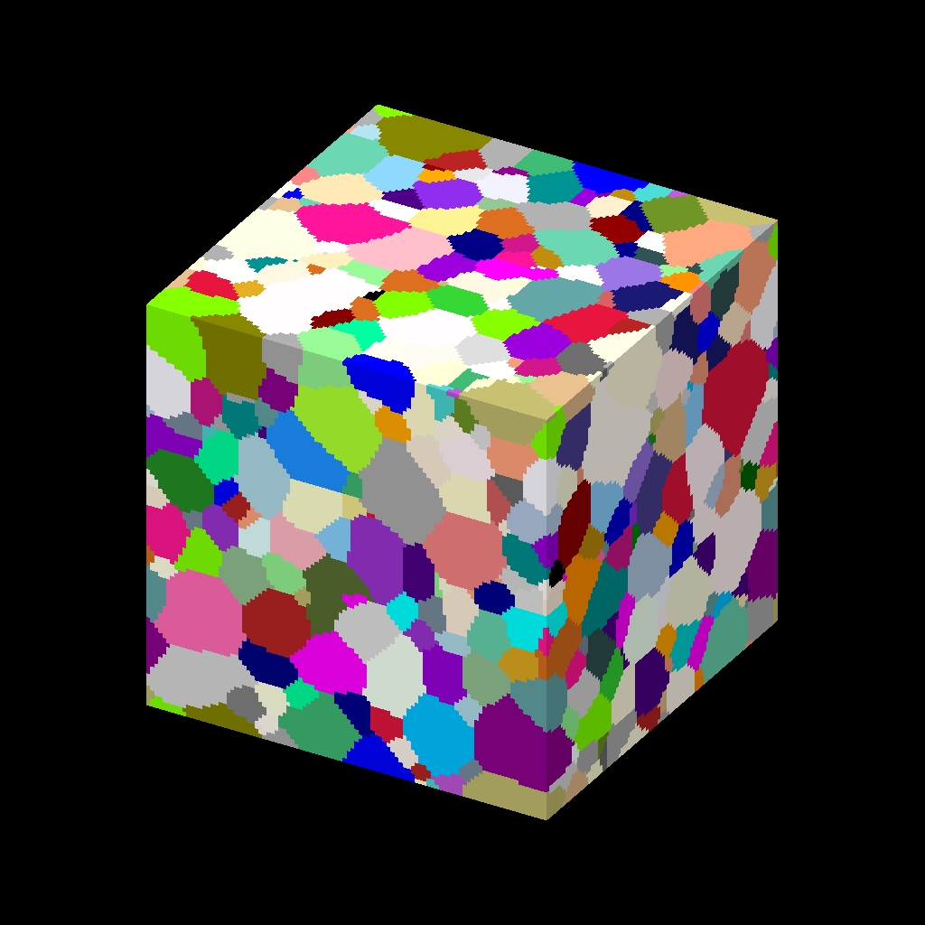
Dump a high-quality ray-traced image of the sites at time intervals of delta during a simulation as either a JPG or PPM file. A series of such images can easily be converted into an animated movie of your simulation; see further details below. The text dump style writes snapshots of numerical data asociated with sites, as discussed on the dump doc page.
Here are two sample images, rendered as 1024x1024 JPG files. The left image is a million-site lattice; the right image is half a billion sites. Click to see the full-size images:
The dump_modify command can be used to alter the times at which images are written out as well as alter what sites are included in the image.
The filename suffix determines whether a JPG or PPM file is created. If the suffix is ".jpg" or ".jpeg", then a JPG file is created, else a PPM file is created, which is a text-based format. To write out JPG files, you must build SPPARKS with a JPEG library. See this section of the manual for instructions on how to do this.
Dump image filenames must contain a wildcard character "*", so that one image file per snapshot is written. The "*" character is replaced with the timestep value. For example, tmp.dump.*.jpg becomes tmp.dump.0.jpg, tmp.dump.10000.jpg, tmp.dump.20000.jpg, etc. Note that the dump_modify pad command can be used to insure all timestep numbers are the same length (e.g. 00010), which can make it easier to convert a series of images into a movie in the correct ordering.
The color and diameter settings determine the color and size of sites rendered in the image. They can be any attribute defined for the dump text command, including site. Note that the diameter setting can be overridden with a numeric value by the optional sdiam keyword, in which case you can specify the diameter setting with any valid atom attribute.
If an integer attribute such as site or i2 is specified for the color setting, then you must use the optional crange keyword to specify the range of integer values that are allowed, from lo to hi. The color of each site is determined by the integer value. By default the mapping of values to colors is done by looping over the set of pre-defined colors listed with the dump_modify command, and assiging the first one to value lo, the next to value lo+1, and so on, repeating the assignment in a loop if the number of values exceeds the number of pre-defined colors. This mapping can be changed by the dump_modify scolor command.
If a floating point attribute such as energy or d1 is specified for the color setting, then the site's attribute will be associated with a specific color via a "color map", which can be specified via the dump_modify command. The basic idea is that the attribute will be within a range of values, and every value within the range is mapped to a specific color. Depending on how the color map is defined, that mapping can take place via interpolation so that a value of -3.2 is halfway between "red" and "blue", or discretely so that the value of -3.2 is "orange".
If an integer attribute such as site or i2 is specified for the diameter setting, then you must use the optional drange keyword to specify the range of integer values that are allowed. The size of each site is determined by the integer value. By default all values has diameter 1.0. This mapping can be changed by the dump_modify sdiam command.
If a floating point attribute such as energy or d1 is specified for the diameter setting, then the site will be rendered using the site's attribute as the diameter. If the per-site value <= 0.0, then the site will not be drawn.
The various keywords listed above control how the image is rendered. As listed below, all of the keywords have defaults, most of which you will likely not need to change. The dump modify also has options specific to the dump image style, particularly for assigning colors to atoms, bonds, and other image features.
The shape keyword can be specied with a value of sphere or cube, to draw either a sphere or cube at each site. Cubes typically only make sense for simple square or cubic lattices with regular spacing, so that the cubes will tile the 2d or 3d space without overlapping. The diameter specified for each site will be the diamter of the sphere or the edge length of the cube.
The sdiam keyword allows you to override the diameter setting with a specified numeric value. All sites will be drawn with that diameter.
The boundary keyword enables drawing of boundaries bewteen neighboring sites that have a different value of the specified attribute. This is a way to visualize the boundary between two contiguous groups of sites based on an attribute that is different for the two groups, even if the sites themselves in the 2 groups are rendered with the same color (due to the value of their color setting).
The specified attribute can be any attribute defined for the dump text command, including site. A boundary is only drawn between site pairs (I,J), where site I is rendered by the dump image command, site J is one of its nearest neighbors, and the value of the specified attribute is different for the 2 sites.
The boundary itself is drawn as 4 cylinders which outline a square. If the 2 adjacent sites are rendered as cubes (via the shape setting), then the square is the face common to the 2 adjacent cubes. The diameter of the cylinders is set via the bdiam keyword. The color of the cylinders can be set via the dump_modify boundcolor command.
The crange keyword must be used if the specified color setting is an integer attribute such as site or i2. The lo and hi values are the range of values that the attribute can have. For example, if spins in a Potts model will range from 1 to 100 (inclusive), then lo and hi should be specified as 1 and 100.
Note that internally the code allocates a vector of color values that is of length hi-lo+1. Thus you may run out of memory if crange encompasses N values and N is very large, e.g. 2 billion. In this case you should choose a smaller N, e.g. 10000, and use the dump_modify cwrap yes command to wrap the 2 billion possible values into N smaller values.
The drange keyword must be used if the specified diameter setting is an integer attribute such as site or i2, unless the sdiam keyword is used, in which case the diameter setting is ignored. The lo and hi values are the range of values that the attribute can have. For example, if the i2 attibute will take on the values -1, 0, or 1, then then lo and hi should be specified as -1 and 1
Note that internally the code allocates a vector of diameter values that is of length hi-lo+1. Thus you may run out of memory if drange encompasses N values and N is very large, e.g. 2 billion. In this case you should choose a smaller N, e.g. 10000, and use the dump_modify dwrap yes command to wrap the 2 billion possible values into N smaller values.
The size keyword sets the width and height of the created images, i.e. the number of pixels in each direction.
The view, center, up, zoom, and persp values determine how 3d simulation space is mapped to the 2d plane of the image. Basically they control how the simulation box appears in the image.
All of the view, center, up, zoom, and persp values can be specified as numeric quantities, whose meaning is explained below. Any of them can also be specified as an equal-style variable, by using v_name as the value, where "name" is the variable name. In this case the variable will be evaluated on the timestep each image is created to create a new value. If the equal-style variable is time-dependent, this is a means of changing the way the simulation box appears from image to image, effectively doing a pan or fly-by view of your simulation.
The view keyword determines the viewpoint from which the simulation box is viewed, looking towards the center point. The theta value is the vertical angle from the +z axis, and must be an angle from 0 to 180 degrees. The phi value is an azimuthal angle around the z axis and can be positive or negative. A value of 0.0 is a view along the +x axis, towards the center point. If theta or phi are specified via variables, then the variable values should be in degrees.
The center keyword determines the point in simulation space that will be at the center of the image. Cx, Cy, and Cz are speficied as fractions of the box dimensions, so that (0.5,0.5,0.5) is the center of the simulation box. These values do not have to be between 0.0 and 1.0, if you want the simulation box to be offset from the center of the image. Note, however, that if you choose strange values for Cx, Cy, or Cz you may get a blank image. Internally, Cx, Cy, and Cz are converted into a point in simulation space. If flag is set to "s" for static, then this conversion is done once, at the time the dump command is issued. If flag is set to "d" for dynamic then the conversion is performed every time a new image is created. If the box size or shape is changing, this will adjust the center point in simulation space.
The up keyword determines what direction in simulation space will be "up" in the image. Internally it is stored as a vector that is in the plane perpendicular to the view vector implied by the theta and pni values, and which is also in the plane defined by the view vector and user-specified up vector. Thus this internal vector is computed from the user-specified up vector as
up_internal = view cross (up cross view)
This means the only restriction on the specified up vector is that it cannot be parallel to the view vector, implied by the theta and phi values.
The zoom keyword scales the size of the simulation box as it appears in the image. The default zfactor value of 1 should display an image mostly filled by the atoms in the simulation box. A zfactor > 1 will make the simulation box larger; a zfactor < 1 will make it smaller. Zfactor must be a value > 0.0.
The persp keyword determines how much depth perspective is present in the image. Depth perspective makes lines that are parallel in simulation space appear non-parallel in the image. A pfactor value of 0.0 means that parallel lines will meet at infininty (1.0/pfactor), which is an orthographic rendering with no persepctive. A pfactor value between 0.0 and 1.0 will introduce more perspective. A pfactor value > 1 will create a highly skewed image with a large amount of perspective.
IMPORTANT NOTE: The persp keyword is not yet supported as an option.
The box keyword determines how the simulation box boundaries are rendered as thin cylinders in the image. If no is set, then the box boundaries are not drawn and the diam setting is ignored. If yes is set, the 12 edges of the box are drawn, with a diameter that is a fraction of the shortest box length in x,y,z (for 3d) or x,y (for 2d). The color of the box boundaries can be set with the dump_modify boxcolor command.
The axes keyword determines how the coordinate axes are rendered as thin cylinders in the image. If no is set, then the axes are not drawn and the length and diam settings are ignored. If yes is set, 3 thin cylinders are drawn to represent the x,y,z axes in colors red,green,blue. The origin of these cylinders will be offset from the lower left corner of the box by 10%. The length setting determines how long the cylinders will be as a fraction of the respective box lengths. The diam setting determines their thickness as a fraction of the shortest box length in x,y,z (for 3d) or x,y (for 2d).
The shiny keyword determines how shiny the objects rendered in the image will appear. The sfactor value must be a value 0.0 <= sfactor <= 1.0, where sfactor = 1 is a highly reflective surface and sfactor = 0 is a rough non-shiny surface.
The ssao keyword turns on/off a screen space ambient occlusion (SSAO) model for depth shading. If yes is set, then atoms further away from the viewer are darkened via a randomized process, which is perceived as depth. The calculation of this effect can increase the cost of computing the image by roughly 2x. The strength of the effect can be scaled by the dfactor parameter. If no is set, no depth shading is performed.
A series of JPG or PPM images can be converted into a movie file and then played as a movie using commonly available tools.
Convert JPG or PPM files into an animated GIF or MPEG or other movie file:
% convert *.jpg foo.gif
% convert *.ppm foo.mpg
Select "Open Image Sequence" under the File menu Load the images into QuickTime to animate them Select "Export" under the File menu Save the movie as a QuickTime movie (*.mov) or in another format
If someone tells us how to do this via a common Windows-based tool, we'll post the instructions here.
Play the movie:
Select "Open File" under the File menu Load the animated GIF file
% mplayer foo.mpg
a = animate("foo*.jpg")
Restrictions:
To write JPG images, you must use a -DSPPARKS_JPEG switch when building SPPARKS and link with a JPEG library. See the Making LAMMPS section of the documentation for details.
Related commands:
Default:
The defaults for the keywords are as follows: